Moving multi-gigabit data across a printed circuit board or copper cable is harder than it looks. As traces get longer and data rates rise, high-frequency components weaken, edges become less distinct, and timing margins shrink.
A quad equalizer is designed to address that problem across four data channels simultaneously. The term commonly refers to a four-channel high-speed signal-conditioning IC rather than a conventional audio equalizer, which matches the dominant technical interpretation of the keyword specified for this article.
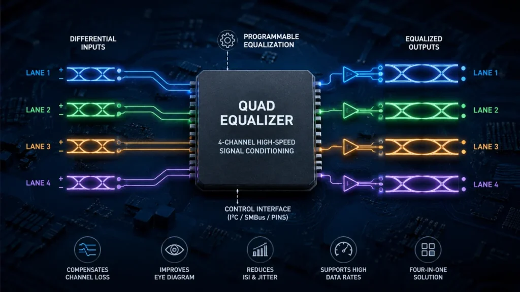
A quad equalizer is an integrated signal-conditioning device containing four equalization channels. It compensates for frequency-dependent losses introduced by PCB traces or copper cables, helping restore high-speed differential signals before they reach a receiver. These devices are commonly associated with interfaces such as PCI Express, DisplayPort, XAUI, InfiniBand, SAS, and SATA.
Understanding what happens inside the device explains why equalization has become so important in high-speed digital hardware.
What Is a Quad Equalizer?
A quad equalizer combines four independent or semi-independent equalization paths in a single integrated circuit.
The word quad refers to the four channels. The word equalizer describes the signal-conditioning circuitry used to compensate for losses in a transmission medium.
Those four channels are particularly useful in interfaces that naturally employ multiple high-speed differential lanes.
For example, Analog Devices’ MAX3980 contains four differential digital data lanes operating at 3.125 Gbps. It was designed for XAUI applications and could compensate for losses over as much as 40 inches of FR4 PCB material.
Other quad equalizers target different protocols and speeds. Texas Instruments’ DS32EV400, for example, provides four data channels and is optimized for operation up to 3.2 Gbps in cable and backplane applications.
The exact capabilities therefore depend heavily on the device.
Quad equalizer does not necessarily mean four frequency bands
This distinction matters.
In audio equipment, a four-band equalizer divides the audible spectrum into four adjustable frequency regions. A high-speed digital quad equalizer generally means something different: four signal lanes being equalized by one IC.
The purpose is signal integrity rather than changing the tonal balance of music.
Why High-Speed Signals Need Equalization
An ideal digital waveform would arrive at the receiver looking almost exactly like the waveform that left the transmitter.
Real interconnects do not behave that way.
PCB traces, connectors and cables introduce losses. These losses are frequency dependent, meaning higher-frequency portions of the signal can experience greater attenuation than lower-frequency components.
That matters because a digital signal is composed of many frequency components.
When high-frequency information is increasingly attenuated, sharp transitions become rounded and adjacent bits begin interfering with one another.
This effect contributes to intersymbol interference (ISI).
The receiver then has a harder time deciding whether each bit represents a logical 1 or 0 at the correct sampling instant.
Equalization compensates for these transmission-medium losses. The MAX3980, for instance, specifically uses receiver equalization to reduce ISI on its four XAUI data lanes.
At higher speeds, the problem becomes even more significant.
Texas Instruments’ DS64EV400 was designed to compensate for transmission losses and medium-induced deterministic jitter across four NRZ channels. Its documentation specifies operation up to 10 Gbps and equalization of up to 24 dB of loss at that rate.
What problems can equalization address?
Depending on the IC and link architecture, equalization can help with:
- Frequency-dependent insertion loss
- Degraded signal edges
- Intersymbol interference
- Reduced eye opening
- Deterministic jitter caused by the transmission medium
- Longer PCB trace lengths
- Longer copper cable connections
- Receiver signal-integrity margins
Equalization does not magically recreate information that has been completely lost. Instead, it compensates for predictable channel characteristics so the receiver sees a cleaner waveform.
How a Quad Equalizer Works
A simplified high-speed link looks like this:
Transmitter → PCB trace/cable → Equalizer → Receiver
The transmitter generates a differential signal. As that signal travels through the interconnect, attenuation changes its shape.
The equalizer applies frequency-selective compensation.
Higher-frequency components that suffered greater attenuation can effectively receive more compensation than lower-frequency components. The resulting waveform is better suited for reliable detection by downstream receiver circuitry.
Inside a quad device, this process happens across four channels.
The DS32EV400 provides a useful example. Each of its four data channels includes an equalizer stage, limiting amplifier, DC offset correction block and CML driver.
1. Differential input receives the degraded signal
High-speed serial links commonly use differential signaling.
Rather than representing data through one signal referenced directly to ground, the receiver examines the difference between a pair of conductors.
Some quad equalizers therefore expose positive and negative inputs for every lane.
The MAX3980 uses 100-ohm differential CML data inputs and outputs across its high-speed signal paths.
2. Equalization compensates for channel loss
The equalizer applies a frequency response intended to counteract the characteristics of the transmission medium.
Imagine a long PCB trace that significantly attenuates the higher-frequency components required to preserve fast transitions.
The equalizer’s response can compensate for that imbalance.
The goal isn’t simply to “boost the signal.”
It is to improve the shape and integrity of the waveform.
3. Additional circuitry conditions the signal
Depending on the design, a device may also incorporate:
- Limiting amplification
- DC offset correction
- Output drivers
- Signal detection
- Input termination
- Output emphasis or pre-emphasis
- Polarity inversion
- Channel enable controls
- Power-management functions
This is why modern devices are often described as equalizers, redrivers or lane extenders rather than simple amplifiers.
4. The conditioned signal continues to the receiver
Once conditioned, the differential output travels toward the destination device.
A properly configured equalizer can increase the usable channel margin and allow signals to operate over interconnects that might otherwise introduce excessive loss.
Four Channels: Why the Quad Architecture Matters
High-speed communication standards frequently transport data over multiple lanes.
Instead of installing a separate IC for every lane, a quad architecture places four equalization channels inside one package.
That can simplify board design while reducing component count.
Consider XAUI.
The MAX3980 was specifically designed around four 3.125 Gbps digital lanes for IEEE 802.3ae XAUI applications.
A similar four-lane architecture appears in other high-speed environments.
Renesas describes its QLX4600-S30 as a quad receive-side equalizer intended for protocols including DisplayPort 1.2, InfiniBand, PCI Express and 10GBASE-CX4, with line rates up to 6.25 Gb/s.
The advantage isn’t simply packaging convenience.
Multiple channels in one device can also provide a consistent signal-conditioning architecture across related lanes.
Programmable Equalization Explained
Not every PCB trace or cable produces the same amount of loss.
A short trace might require little compensation, while a long cable could need considerably more.
That is why many quad equalizers offer programmable equalization.
Instead of applying one fixed response, engineers can select a compensation level that better matches the physical channel.
The DS64EV400, for example, provides eight programmable equalization levels. Its channels can be configured through control pins or individually through an SMBus interface.
The QLX4600-S30 goes further by providing 32 compensation levels for each of its four equalizing filters. Renesas states that settings can be controlled through external pins or a serial bus interface.
Fixed vs. programmable equalization
| Feature | Fixed Equalization | Programmable Equalization |
|---|---|---|
| Configuration | Predetermined | Adjustable |
| Design complexity | Lower | Higher |
| Flexibility | Limited | Greater |
| Channel optimization | Basic | More precise |
| Best suited for | Predictable channels | Variable trace/cable losses |
More settings aren’t automatically better.
The useful setting is the one that provides appropriate compensation for the actual channel.
Too little equalization may leave substantial high-frequency loss uncorrected. Excessive compensation can also degrade signal quality rather than improve it.
Quad Equalizer vs. Redriver
The terms equalizer and redriver often appear together, but they describe related rather than identical concepts.
An equalizer primarily compensates for channel-induced frequency loss at the receiving side.
A redriver conditions and retransmits the signal so it can continue through another section of the channel.
Modern ICs frequently combine these functions.
The MAX14950 is a good example. Analog Devices describes it as a quad PCI Express equalizer/redriver. It uses programmable input equalization at the receiver and programmable redrive circuitry at the output.
The device supports PCIe Gen III at 8.0 GT/s, Gen II at 5.0 GT/s and compatibility with Gen I at 2.5 GT/s.
Its output circuitry also restores emphasis lost through the PCB and compensates for circuit-board loss.
So the distinction can be summarized simply:
Equalization improves the incoming waveform; redriving prepares a regenerated or conditioned output for the next part of the link.
An IC may perform both jobs.
Equalization, Pre-Emphasis and De-Emphasis
These terms can easily become confusing because all three influence high-frequency signal behavior.
Receive equalization
Receive equalization occurs toward the receiving side of a channel.
Its job is to compensate for losses that have already occurred while the signal traveled through the transmission medium.
Pre-emphasis
Pre-emphasis modifies the transmitted waveform so certain components are emphasized before the signal encounters channel loss.
The MAX3987 combines four-channel receive equalization with transmit pre-emphasis functionality. It supports data speeds up to 8.5 Gbps and was designed to compensate for significant FR4 interconnect loss.
De-emphasis
De-emphasis changes the relative signal amplitude following transitions, helping compensate for the frequency response of the channel.
The older MAX4950 PCIe equalizer/redriver, for example, provides programmable input equalization together with programmable output de-emphasis.
These techniques attack the same broad signal-integrity problem from different points in the transmission path.
Where Quad Equalizers Are Used
Quad equalizers are most useful when multiple high-speed differential channels must travel through lossy copper interconnects.
Common applications include the following.
PCI Express
PCIe data rates make PCB routing and signal integrity increasingly demanding.
Devices such as the MAX14950 were designed specifically to improve PCI Express signal integrity across board traces and related interconnects. Analog Devices specifies programmable input equalization and output emphasis for this purpose.
DisplayPort
DisplayPort is another multi-lane high-speed interface where cable attenuation can become significant.
The DS32EV400 has been evaluated as an active equalizer for extending DisplayPort cable reach. A National Semiconductor application report found that adding the device in its test configuration extended total cable reach to approximately 12 meters, compared with roughly 6–8 meters using the tested source and display’s built-in conditioning alone. Results depend on cable quality and system design, so this should not be treated as a universal DisplayPort distance guarantee.
XAUI and 10 Gigabit Ethernet
XAUI uses four lanes, making quad equalization a natural architecture.
The MAX3980 supports four 3.125 Gbps lanes and was developed around IEEE 802.3ae XAUI backplane applications.
Its related MAX3981 was designed for cable applications and could support four 3.125 Gbps lanes across up to 10 meters of twin-axial cable under its specified conditions.
SAS and SATA
High-speed storage links can also benefit from receive equalization and redrive circuitry.
The MAX3987 supports applications involving SAS-2 and SATA Revision 3 OOB, alongside several other high-speed protocols.
InfiniBand
Several equalizer families have also targeted InfiniBand.
The MAX3980 lists 2.5 Gbps InfiniBand among its applications, while the QLX4600-S30 supports InfiniBand SDR and DDR environments.
Cable Equalization vs. Backplane Equalization
Although both involve transmission loss, cables and PCB backplanes do not necessarily have identical characteristics.
Backplane equalization
A PCB backplane may contain:
- Long FR4 traces
- Vias
- Connectors
- Layer transitions
- Impedance discontinuities
As data rates increase, these elements can reduce the available signal margin.
Equalizers designed for backplanes compensate for the associated frequency-dependent attenuation.
Cable equalization
Copper cables introduce their own attenuation characteristics.
Cable length, conductor size, connector quality and cable construction all influence the amount of loss.
A cable equalizer therefore needs compensation appropriate for the targeted cable environment.
The QLX4600-S30, for example, is specified to compensate for frequency-dependent attenuation in copper twin-axial cables and can extend reach up to 30 meters on 24-AWG cable under the manufacturer’s specified conditions.
Quick takeaway: Equalization capability should always be evaluated against the actual transmission medium. A device being capable of substantial compensation does not mean every PCB or cable can automatically operate at its maximum advertised distance.
Important Specifications to Understand
Selecting or evaluating a quad equalizer requires more than checking its maximum data rate.
Several parameters matter.
Maximum data rate
The equalizer must support the intended signaling speed.
Examples across different generations show how widely this can vary:
| Device | Example Capability |
|---|---|
| MAX3980 | Four lanes at 3.125 Gbps |
| DS32EV400 | Up to 3.2 Gbps |
| QLX4600-S30 | Up to 6.25 Gb/s |
| MAX3987 | Up to 8.5 Gbps |
| DS64EV400 | Up to 10 Gbps |
Raw speed alone, however, doesn’t establish compatibility with a particular protocol.
Equalization range
This indicates how much channel loss the device is designed to compensate for under specified conditions.
The DS64EV400, for example, specifies equalization of up to 24 dB of loss at 10 Gbps and up to 22 dB at 6.4 Gbps.
Number of equalization settings
More programmable levels allow finer tuning.
Some devices provide a handful of levels, while others provide considerably more.
Input and output termination
Correct impedance matching is essential in high-speed differential links.
For example, several devices in this class use 100-ohm differential signaling environments or integrated termination structures.
Jitter performance
Jitter describes variation in signal transition timing.
A link may have sufficient voltage amplitude but still fail if timing uncertainty becomes excessive.
For that reason, datasheets may specify deterministic jitter, random jitter, total jitter or residual deterministic jitter under particular test conditions.
Propagation delay
Signal-conditioning circuitry introduces some delay.
The MAX14950, for example, specifies a typical propagation delay of 160 ps.
This may matter in systems with tight latency or lane-matching requirements.
Power consumption
Four high-speed analog channels can consume meaningful power.
Older devices illustrate this clearly. The MAX3980 specifies 175 mW per channel and approximately 700 mW total operation from a 3.3 V supply.
Power becomes especially important when many equalizers are used on a densely populated board.
How Do You Choose the Correct Equalization Setting?
The best equalization level is not simply the highest available setting.
It should correspond to the actual loss characteristics of the channel.
A practical engineering process generally looks like this:
- Determine the protocol and data rate.
- Estimate or simulate channel insertion loss.
- Choose an equalizer supporting the required frequency and loss range.
- Start with a compensation level appropriate for the expected channel loss.
- Measure the resulting signal quality.
- Adjust equalization while observing eye opening, jitter and receiver performance.
- Validate the design across process, voltage, temperature and realistic interconnect variations.
Some systems use pin-controlled settings. Others allow software configuration through interfaces such as SMBus or I²C.
The DS64EV400 supports SMBus programming, while the MAX3987 offers both hardware and software-controlled operation, including I²C-based configuration.
Common Quad Equalizer Design Mistakes
Adding an equalizer does not automatically solve every signal-integrity problem.
Several mistakes can undermine an otherwise capable device.
Applying too much equalization
If the physical channel has modest loss but aggressive compensation is applied, the resulting waveform may become over-equalized.
More boost is not inherently better.
Ignoring PCB layout
Equalization cannot compensate for every layout defect.
Poor impedance control, badly placed vias, unnecessary stubs, excessive crosstalk and badly designed connector transitions can still create problems.
High-speed input and output traces should follow the layout recommendations in the specific manufacturer’s datasheet.
Treating all four lanes identically without verification
Four lanes routed through the same board can still have different lengths or discontinuities.
Devices offering individual channel control can be particularly useful when lane losses differ.
Looking only at maximum data rate
A “10 Gbps” label doesn’t automatically mean an equalizer is suitable for every 10 Gbps protocol.
Electrical requirements, encoding, receiver behavior, output characteristics and protocol-specific features must also be considered.
Ignoring device lifecycle
This point is particularly important when researching older quad equalizers.
Some well-known devices remain useful for understanding the technology but are no longer appropriate for new designs. Analog Devices currently lists the MAX3980 as not recommended for new designs, while MAX3981, MAX4950 and MAX3987 are listed as obsolete.
Engineers designing new hardware should verify the current product lifecycle and manufacturer recommendations rather than selecting a part solely because an older application note or reference design uses it.
Does a Quad Equalizer Increase Transmission Distance?
Potentially, yes—but the answer needs context.
An equalizer can compensate for channel attenuation, which may allow a high-speed signal to travel farther through a PCB trace or cable while maintaining adequate signal integrity.
Examples demonstrate the principle.
The MAX3980 was designed to support XAUI operation across up to 40 inches of FR4. The MAX3981 targeted up to 10 meters of twin-axial cable. Renesas specifies cable reach of up to 30 meters on 24-AWG cable for the QLX4600-S30 under applicable operating conditions.
But those figures cannot simply be transferred to another system.
Actual reach depends on:
- Data rate
- Cable construction
- PCB material
- Trace geometry
- Connector loss
- Channel insertion loss
- Equalization setting
- Transmitter characteristics
- Receiver sensitivity
- Jitter budget
- Environmental conditions
Think of equalization as recovering signal margin, not guaranteeing a particular distance.
How Is Equalizer Performance Verified?
Engineers normally evaluate equalization in terms of the quality of the resulting high-speed signal rather than simply asking whether a waveform appears at the output.
One common visualization is an eye diagram.
Repeated bit transitions are overlaid on an oscilloscope display, producing an eye-shaped opening. Severe attenuation, ISI and jitter can cause that opening to shrink.
Effective signal conditioning should provide sufficient voltage and timing margin for the receiver to make reliable decisions.
Other measurements and validation methods may include:
- Bit-error-rate testing
- Jitter measurements
- Insertion-loss analysis
- S-parameter measurements
- Channel simulation
- Receiver compliance testing
- Protocol-specific compliance testing
Testing should represent the complete channel rather than the equalizer in isolation.
That includes the transmitter, PCB traces, connectors, cables, equalizer and receiver.
What a Quad Equalizer Cannot Fix
Equalization is powerful, but it has limits.
It cannot compensate indefinitely for an arbitrarily poor channel.
If attenuation is excessive, the signal-to-noise ratio may already be too low. Reflections from severe impedance discontinuities can create distortions that simple equalization cannot fully remove. Crosstalk and power-integrity problems may introduce additional noise.
Equalizers also cannot correct logical or protocol errors.
If the transmitter sends incorrect data, signal conditioning merely produces a cleaner version of the wrong waveform.
A reliable design therefore combines equalization with:
- Controlled-impedance routing
- Appropriate termination
- Low-loss interconnects where necessary
- Careful connector selection
- Proper power delivery and decoupling
- Crosstalk management
- Channel simulation
- Physical measurements
- Protocol compliance testing
The equalizer is one part of the signal-integrity strategy.
Quad Equalizer vs. Repeater or Retimer
Another useful distinction is between an equalizer/redriver and a retimer.
A conventional equalizer primarily performs analog signal conditioning. A redriver may equalize and retransmit the signal without fully recovering its original timing.
A retimer goes further by recovering clock and data before transmitting a newly timed signal.
That distinction becomes important when jitter has accumulated beyond what simple analog conditioning can adequately handle.
A redriver or quad equalizer can be attractive when low latency, relatively simple implementation and channel-loss compensation are the primary requirements.
A retimer may be more appropriate when the system requires stronger jitter cleanup or a fundamentally refreshed timing domain.
The correct choice depends on the link budget and protocol requirements.
The Role of Quad Equalizers in Modern Signal Integrity
High-speed serial links continue to push more data through physically constrained systems.
At lower signaling rates, relatively long PCB traces may behave adequately without much additional conditioning. At multi-gigabit speeds, the interconnect itself becomes a major part of the electrical design.
That is where equalization earns its place.
A quad equalizer provides four channels of signal-loss compensation within one integrated device, helping preserve reliable differential communication across lossy PCB traces and copper cables. Depending on the implementation, it may also provide programmable boost, limiting amplification, signal detection, redrive circuitry, pre-emphasis, de-emphasis, power management and software-controlled configuration.
Devices developed for XAUI, PCI Express, DisplayPort, InfiniBand, SAS, SATA and other high-speed interfaces demonstrate how broadly the underlying principle can be applied.
The key is to treat equalization as part of the complete channel rather than as a universal repair tool. Start with good PCB and interconnect design, understand the expected channel loss, select a device appropriate for the actual protocol and data rate, and validate the finished link through measurement.
When those pieces are handled correctly, a quad equalizer can provide the extra signal margin needed to make demanding four-lane high-speed links work reliably.